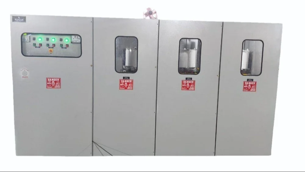
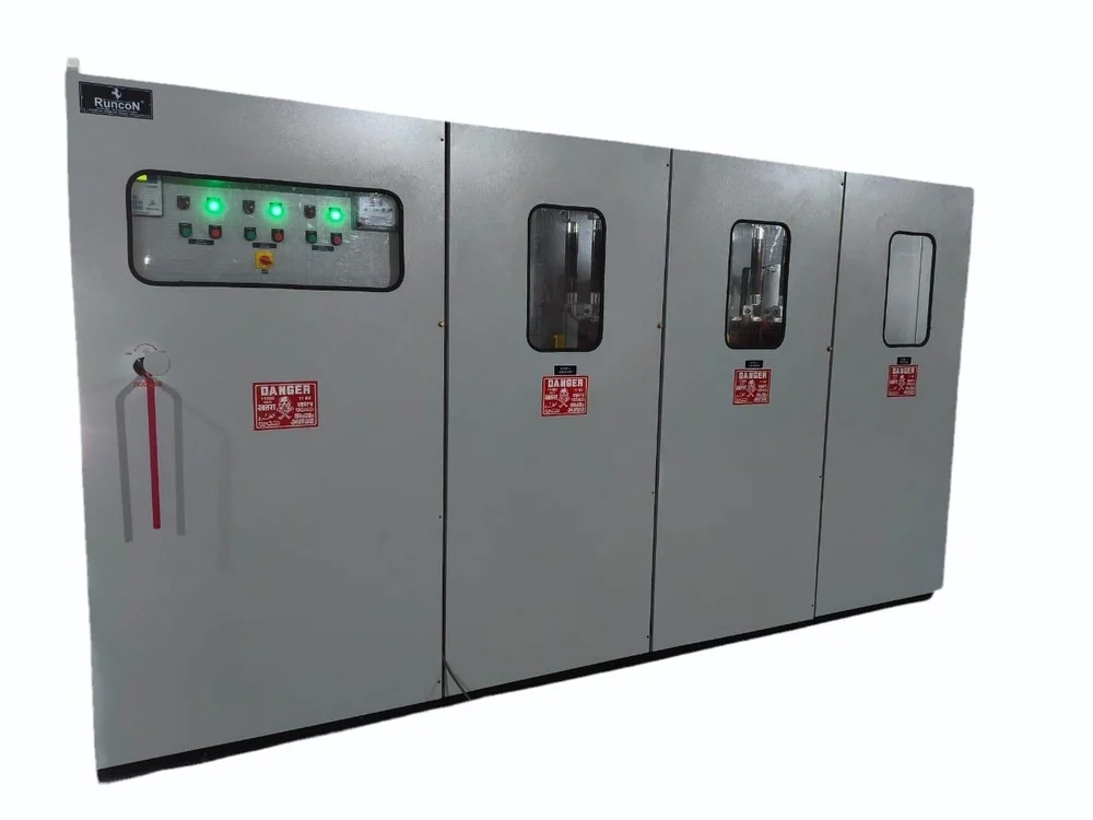
HT APFC PANEL
RuncoN HT APFC Panel (High Tension Automatic Power Factor Control Panel) is used in high-voltage electrical systems to automatically improve power factor by controlling capacitor banks.
What It Does
- Maintains power factor close to unity (≈1.0)
- Reduces reactive power (kVAR)
- Avoids penalties from utilities
- Improves system efficiency
Working Principle
The panel continuously measures power factor using a controller. When PF drops due to inductive loads like motors, it switches ON capacitor banks.
- Inductive loads produce a lagging power factor.
- Capacitors provide leading reactive power to compensate.
- The net effect is an improved power factor.
Step-by-Step Working
- Sensing: CTs (Current Transformers) measure load current and voltage is sensed from the HT line.
- Controller Action: The APFC relay calculates real-time power factor.
- Decision: If PF is low, the controller sends a switching signal.
- Switching: Capacitor banks are switched ON/OFF using vacuum contactors or circuit breakers at HT level.
- Correction: Reactive power is compensated and power factor improves.
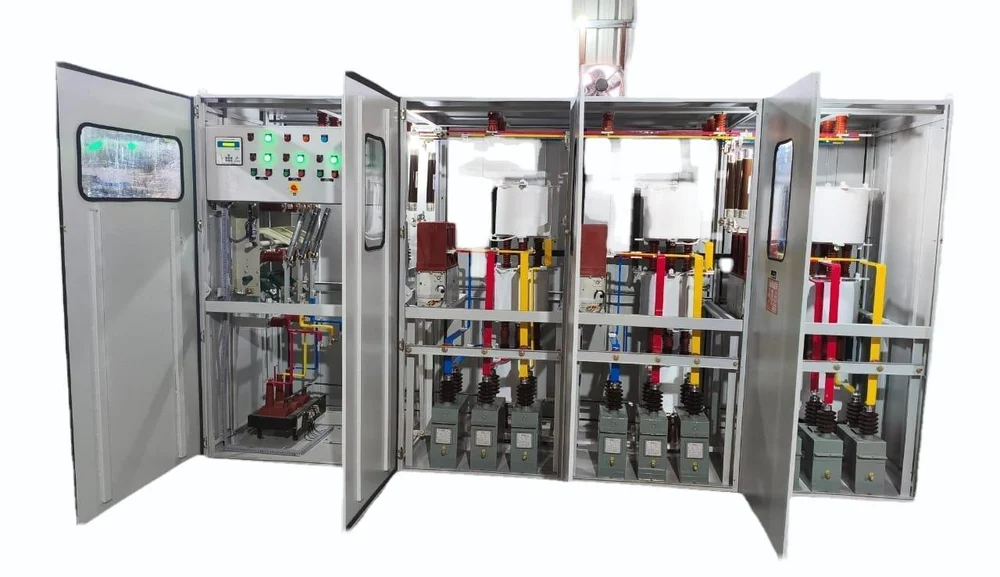
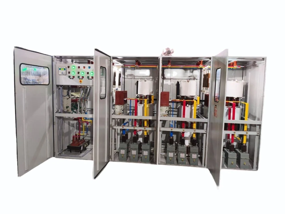
Main Components
- APFC Relay (controller)
- Capacitor banks (HT rated)
- Vacuum Circuit Breakers (VCB)
- Current Transformers (CTs)
- Protection relays
- Busbars and panel structure
Typical Ratings
| Parameter | Value |
|---|
| Voltage | 3.3 kV, 6.6 kV, 11 kV, 33 kV |
| Capacitor Bank Size | 100 kVAR to several MVAR |
Applications
- Large industries
- Steel plants
- Cement plants
- Substations
- Large commercial complexes